Skip to main content
Link
Menu
Expand
(external link)
Document
Search
Copy
Copied
NI HIL System Design Guide
NI HIL System Applications
What is HIL Simulation
Why Use HIL Simulation
HIL Test Applications
Challenges and Mitigation
NI HIL and SDV Architectures
Trends and Observations
Shifting Vehicle Core Technology
Exponential Growth in Software Complexity
Challenge of Software Quality in Vehicle Development
Why NI for HIL?
Software Design Guide
Modeling Frameworks
Framework Architecture
Framework Life Cycle
MIL/SIL Development
Transition to HIL
Compiler Set Up
Plant Model Preparation
Plant Model Compile
Plant Model Import
Vehicle Network Simulation
Restbus Simulation
MVB
TRDP
ECU IO Interface
Signal Routing
Manual Mapping
Programmatic Mapping
Integrating Virtual ECUs
Introduction
Why Virtual ECUs
vECU Abstraction Levels
NI Support for Virtual ECUs
Virtual ECU Toolkit
Installation and Licensing
Importing and Configuring Virtual ECUs
Virtual-to-Real Bus Integration
Hardware Design Guide
Key Benefits
System Architecture Overview
Open Extensible Platform
Complete Hardware Stack
Extended Functionality
Connection to DUT
PXI Platform Overview
PXI Chassis
PXI Controller
Automotive Buses
FPGA
Digital IO
Analog IO
Data Acquisition
SLSC Platform Overview
SLSC Modules
RTI
B061 RTI
B062 RTI
B071 RTI
B092 RTI
B094 RTI
Programmable Power and Load Devices
Programmable Power Supplies
Electronic Load Devices
Rack Options
Signal Paths
Which HIL Platform?
HIL
Analog Input
Simple AI, no FIU
AI High-Current with FIU
AI Low-Current with FIU
Differential AI with FIU
Analog Output
Simple AO, no FIU
AO High-Current with FIU
AO Low-Current with FIU
Digital IO
DIO, No FIU
Digital IO, High-Current with FIU
Digital IO, Low-Current with FIU
PWM
PWM DIO, with FIU
PWM DO, with FIU
PWM DI, with FIU
Sensor Emulation
UEGO Simulator
Wheel Speed Sensor Emulation
Resistor Emulator
Resistor Emulator High Range
Resistor Emulator Low Range
Automotive Vision
Automotive Bus
Automotive Ethernet
100Base-T1
1000Base-T1
100/1000Base-T1
100Base-T1 with FIU
CAN
CAN, no FIU
CAN with FIU
LIN
LIN, no FIU
LIN with FIU
DSI3
Power Switch
CompactHIL
Analog Input (CompactHIL)
Simple AI, no FIU
AI Low-Current with FIU
Analog Output (CompactHIL)
Simple AO, no FIU
AO Low-Current with FIU
Digital IO (CompactHIL)
DIO, No FIU
Digital IO, Low-Current with FIU
PWM (CompactHIL)
PWM DIO, no FIU
Sensor Emulation (Compact HIL)
Resistor Emulator (CompactHIL)
Automotive Bus (CompactHIL)
CAN CompactHIL
CAN, no FIU
LIN CompactHIL
LIN, no FIU
Power Switch
Standalone Components
Charging Simulator Signal Path
Example Projects
MIL/SIL Demo
HIL Demo
Windows HIL Demo
Real-time HIL Demo
Windows Host PC
Install VeriStand
Install VCOM
Real-Time Target
Install RT OS
Install Target SW
Configure CAN Port
How-To Videos
NI HIL Partners
Search NI HIL System Design Guide
Software Design Guide
Signal Routing
Manual Mapping
Manual Signal Mapping with the Graphical User Interface
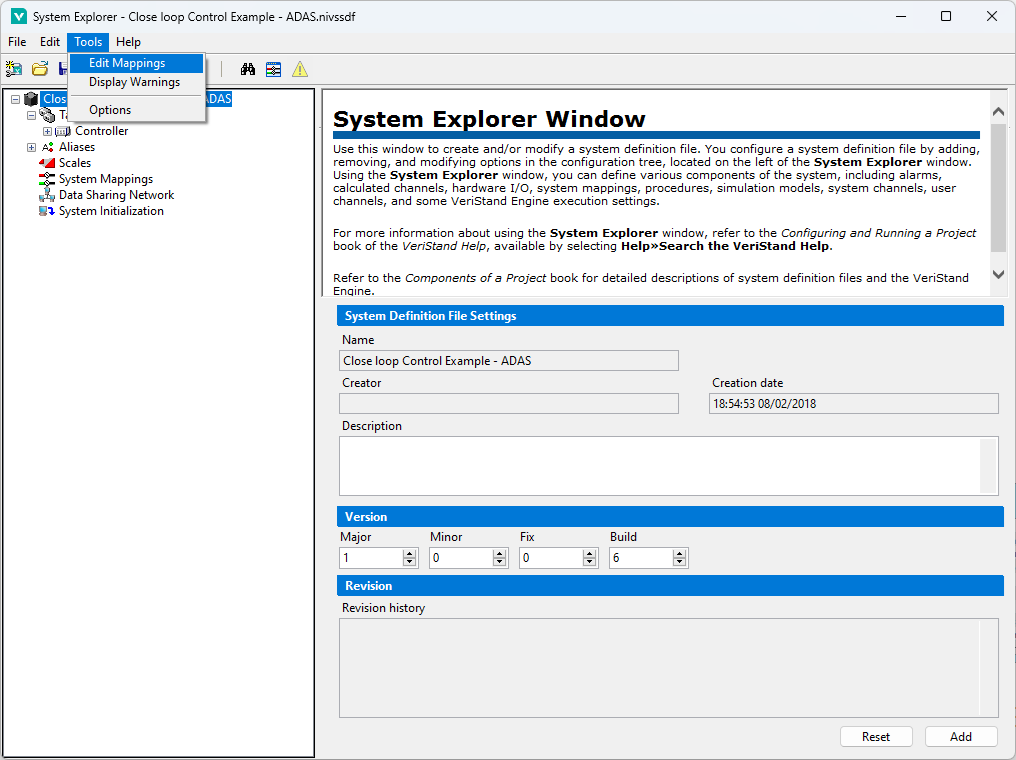
Launch VeriStand.
Open system definition file in System Explorer.
Select Tools»Edit Mappings from the menu.
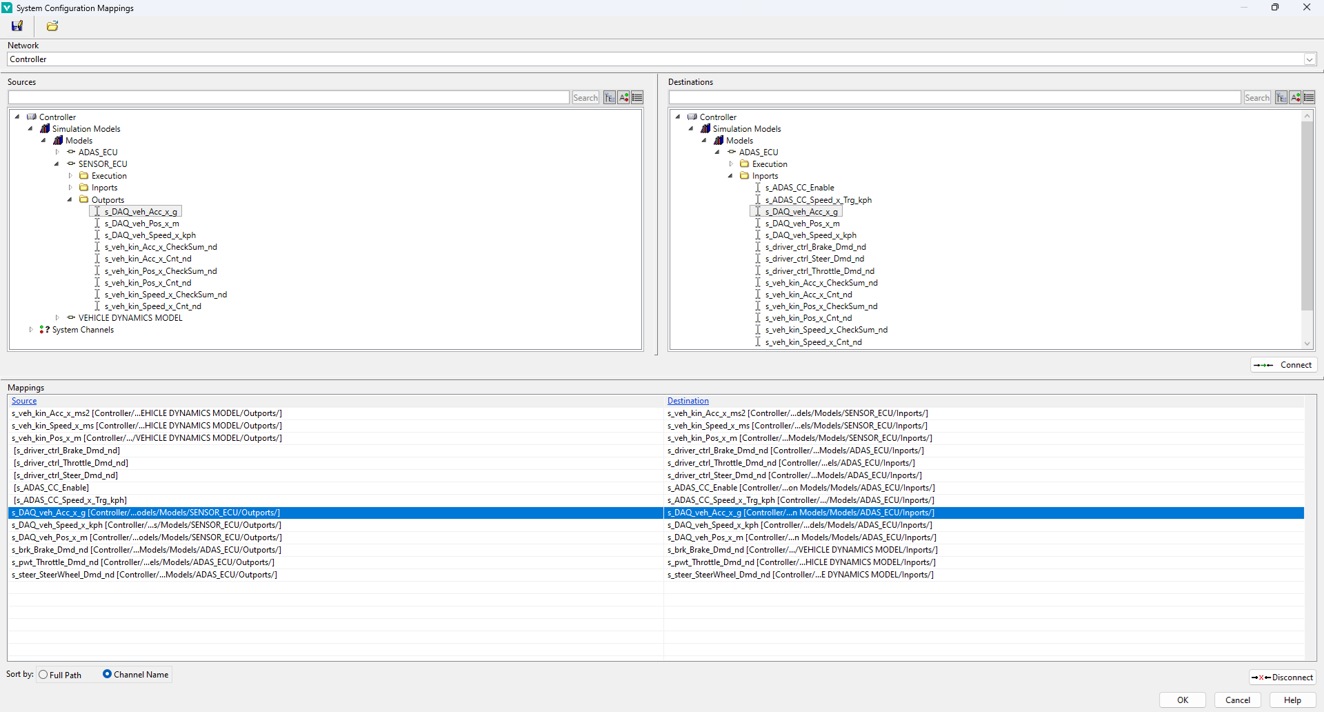
Use the System Configuration Mappings window to connect and disconnect different signals.