Ultrasonic Sensor Simulation
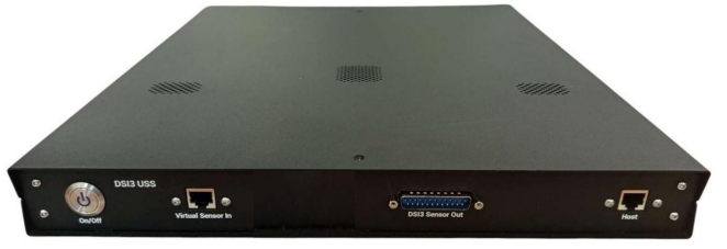
Modern vehicles are equipped with multiple features for driving assistance. One such feature is the Park Assist System (Parktronic), which helps drivers easily locate free parking spaces and perform accurate and safe parking. This system utilizes multiple ultrasonic sensors installed on the front and rear bumpers, along with an advanced, high-technology parking control module (Ultrasonic ECU) that enables these capabilities. The RIPL DSI3 USS Ultrasonic Sensor Simulator can emulate up to 16 ultrasonic sensors using the 3rd Distributed Systems Interface (DSI3) to test the functionality of the parking control module.
Reyocto’s USS solution offers two possible approaches for ECU validation:
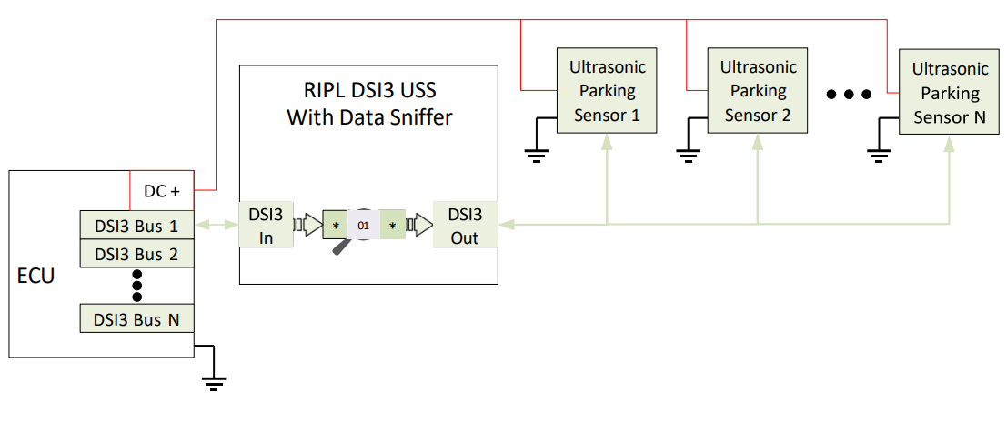
- Sensor Simulation (Without a Physical Sensor in the Loop) In this approach, we simulate the complete ultrasonic sensor using the USS board, without requiring a physical sensor to be connected to the system. Initially, we can use the DSI3 Sniffer to capture and analyze the communication between the ECU and the actual sensor. This helps us identify the necessary configurations and communication parameters. Based on this information, the USS can be configured to emulate the sensor and send simulated responses to the ECU.
- Physical Sensor in the Loop with Fault Injection In this approach, the physical ultrasonic sensor remains connected in the loop. The sensor communicates with the USS board, where we can introduce the required faults into the sensor communication and transmit the resulting responses to the ECU. This approach allows us to validate the ECU’s behavior under normal sensor operating conditions as well as under fault conditions. Both approaches can be used for ECU validation, depending on the testing requirements and whether the objective is complete sensor emulation or fault injection into communication involving a physical sensor.
Attributes
| Attribute | Value |
|---|---|
| Modes | CRM, PDCM, BDM (on demand) |
| Sensor simulation/ device | 16 |
| Channels/signal path | 4, 8 or 12 |
| Topologies | Point-to-Point (1x12) Parallel (3x4ch, 4x3ch, 4x4ch, 2x6ch) |
| Interface to HIL | Ethernet |
| Device Control | UDP |
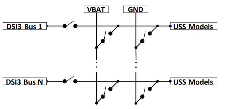
| FIU | Short-to-Ground, Short-to-VBAT, Cross-Connection between buses |
| Data Sniffing | up to 4 independent buses |
| Output Latency | 0.2 to 1ms |
Components
| Component | Model | Specification | Part Number |
|---|---|---|---|
| USS Simulator | RIPL DSI3 | Specification | RIL-DSI3-USS-4xB RIL-DSI3-USS-8xB RIL-DSI3-USS-12xB |
| USS Simulator + FIU* | RIPL DSI3 | Specification | RIL-DSI3-USS-FI4 RIL-DSI3-USS-FI8 RIL-DSI3-USS-FI12 |
| USS Simulator + Sniffer** | RIPL DSI3 | Specification | RIL-DSI3-USS-DSN1 |
*FIU is an option that can be purchased separately.
**Sniffing is an option that can be purchased separately.
Connection Diagram
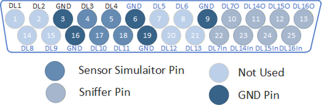
Pinout
| Pin | Signal | Description |
|---|---|---|
| 1 | DL1 | Data Line 1 |
| 2 | DL2 | Data Line 2 |
| 3 | GND | Ground |
| 4 | DL3 | Data Line 3 |
| 5 | DL4 | Data Line 4 |
| 6 | GND | Ground |
| 7 | DL5 | Data Line 5 |
| 8 | DL6 | Data Line 6 |
| 9 | GND | Ground |
| 10 | DL7-OUT | Data Line 7 Output — Sniffer Ch.1 |
| 11 | DL14-OUT | Data Line 14 Output — Sniffer Ch.2 |
| 12 | DL15-OUT | Data Line 15 Output — Sniffer Ch.3 |
| 13 | DL16-OUT | Data Line 16 Output — Sniffer Ch.4 |
| 14 | DL8 | Data Line 8 |
| 15 | DL9 | Data Line 9 |
| 16 | GND | Ground |
| 17 | DL10 | Data Line 10 |
| 18 | DL11 | Data Line 11 |
| 19 | GND | Ground |
| 20 | DL12 | Data Line 12 |
| 21 | DL13 | Data Line 13 |
| 22 | DL7-IN | Data Line 7 Input — Sniffer Ch.1 |
| 23 | DL14-IN | Data Line 14 Input — Sniffer Ch.2 |
| 24 | DL15-IN | Data Line 15 Input — Sniffer Ch.3 |
| 25 | DL16-IN | Data Line 16 Input — Sniffer Ch.4 |
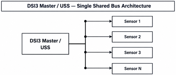
Topologies
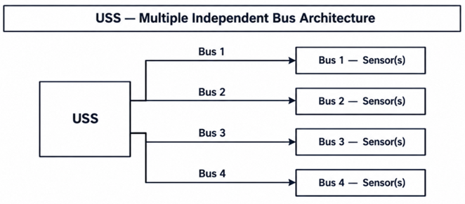
Block Diagram
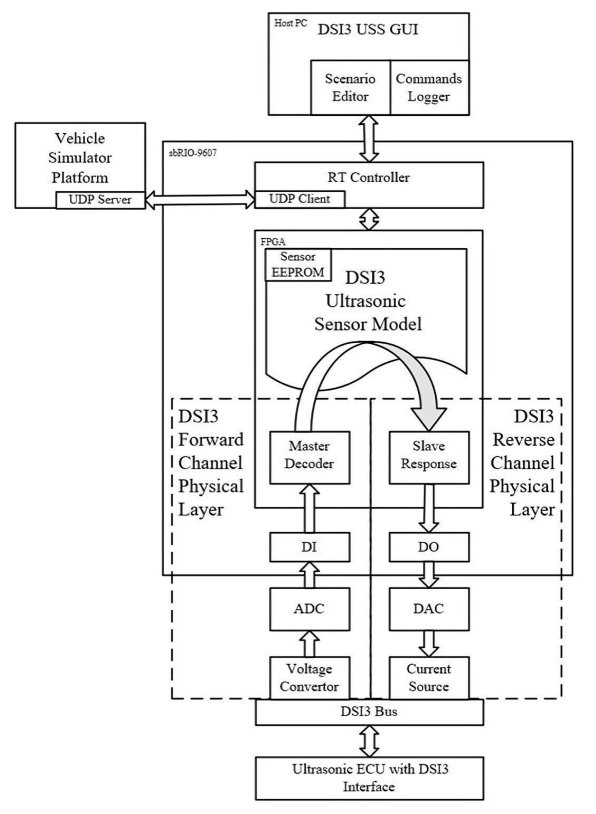
Sniffer Configuration
FIU Configuration