Multifunction Vehicle Bus
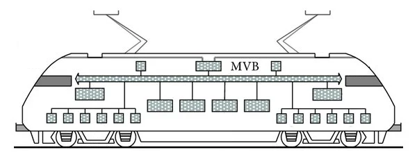
MVB (Multifunction Vehicle Bus) is a communication network used in the railway industry to connect and exchange data between onboard train systems usually within single vehicle (e.g. Locomotive).
It is a key part of the Train Communication Network (TCN) and provides reliable, real-time data communication between various subsystems such as braking control, door control, traction and propulsion systems. It also supports communication with safety systems like train protection and monitoring functions.
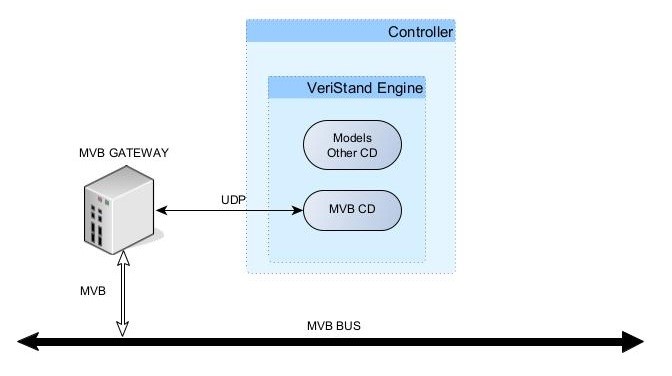
The MVB custom device allows VeriStand to access MVB bus using hardware extensions:
1) MVB GW by Duagon (preferred option)
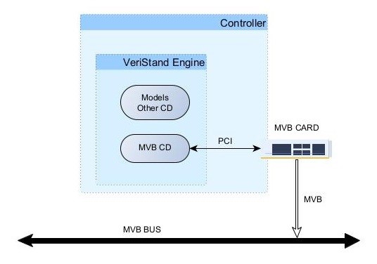
2) PCI extensions cards
Supported devices
- Duagon D451 and D503 ETH-MVB gateways (UDP)
- Duagon D113, D221 and D215 (PCI)
- Custom driver (UDP)
Configuration
The MVB custom device has following options:
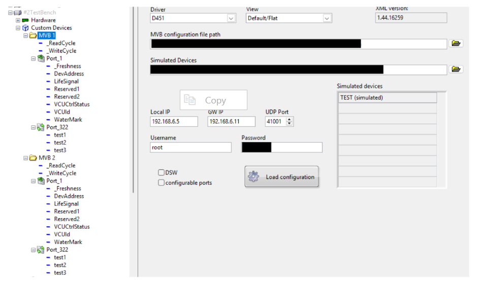
| Driver | Specifies the driver type. |
|---|---|
| Disabled | Disables any communication. Used for VeriStand channels creation. |
| D451 (UDP) | Creates configuration file and communicate with Duagon D451 gateway. Includes DSW, configurable ports. |
| D503 (UDP) | Creates configuration file and communicate with Duagon D503 gateway. |
| Duagon Srv1 (DLL) | Communicates with Duagon MVB cards (e.g. D215) using Server1 architecture. Includes VISA name options. |
| Duagon Srv2 (DLL) | Communicates with Duagon MVB cards (e.g. D113) using Server2 architecture. Includes VISA name options. |
| Simulated (UDP) | Communicates on defined UDP port with any source. Allows to use virtual MVB without real HW |
| View | Specifies the channel grouping options. Change in view type requires reloading the configuration. |
|---|---|
| Default/Flat | MVB Veristand channels are grouped by port address |
| GroupByDirection | MVB Veristand channels are grouped by direction (input/output) then by port address |
| GroupByDevice | MVB Veristand channels are grouped by device name then by port address |
| UI Component | Description |
|---|---|
| XML version | Displays the version of the installed MVB custom device. |
| MVB configuration file path | File path to JSON file with bus configuration |
| Simulated Devices | Displays the loaded devices. |
| VISA name | VISA resource where MVB card is installed (e.g. PXI18::12::INSTR) |
| Local IP | IP address of the interface (local or controller) connected to gateway |
| GW IP | IP address of gateway |
| UDP Port | Port used for UDP communication |
| Username/Password | Credential used for gateway logging |
| DSW | Enable option to send device status word |
| configurable ports | Enable option to dynamically switch on/off port generation (only source ports) |
| Load configuration | Allows user to load a pre-defined configuration file. |
Example MVB Configuration File
Example JSON file describing MVB configuration
"Ports":[
{
"ID":1,
"Size":1,
"Cycle":512,
"Sender":"Device1",
"Signals":[
{
"Offset":0,
"Name":"Reserved1",
"Type":"BOOLEAN1"
},
{
"Offset":1,
"Name":"Reserved2",
"Type":"UNSIGNED8"
}
],
"Receivers":["Device1","Device2","Device3"]
}
],
"Devices":[
{"Name":"Device2","Address":2},
{"Name":"Device3","Address":3}
]
`}
Ports
In the MVB configuration file, Ports describes the MVB telegram definition as an array.
| Attribute | Description |
|---|---|
| ID | port address (DEC) |
| Size | Specifies the port size. Enter 0, 1, 2, 3, or 4, where 0=2 bytes, 1=4 bytes, 2=8bytes, 3=16 bytes, and 4=32 bytes |
| Cycle - port cycle (ms) | |
| Sender | - sending device name |
| Signals | Specifies port variable array inside the Ports array. |
Signals
In the MVB configuration file, Signals describes the signal definition as an array.
| Attribute | Description |
|---|---|
| Offset | Specifies the offset of the variable. |
| Name | Specifies the variable name. |
| Type | Specifies the variable type (according to IEC 61375-1 Table A.5 Type equivalence). |
Receivers
In the MVB configuration file, Receivers is an array of devices registered on current port.
Devices
In the MVB configuration file, Devices is an array of all devices with corresponding addresses.
| Attribute | Description |
|---|---|
| Name | device name |
| Address | device address (DEC) |
Simulated Devices
Example JSON file. Used for determining direction of MVB telegrams.
[
{"device":"Device1","mode":"Simulated"},
{"device":"Device2","mode":"Observed"}
]
If device is set to Simulated mode, the MVB port direction will be assigned based on Sender/Receivers fields from configuration.
If device is set to Observed mode, the MVB port direction will be always set as sink (output) with no possibility of writing data.
Diagnostic channels
The MVB custom device creates several diagnostic channels.
| Channel | Description |
|---|---|
| ReadCycle | Cycle of data exchange between VeriStand and MVB thread. If increasing no data were received |
| Write Cycle | Cycle of data exchange between VeriStand and MVB thread. If increasing no data were send |
| Freshness | Only for read telegrams. Value in [ms] shows when data were refreshed on MVB bus e.g. 100: data received 100ms ago, 65535: data never received |
| Enabled | Only for send telegrams when option is configurable ports is enabled. Enable/Disable sending data on given port |
| DSW/Device | Only for DSW option. Allows to send given value of device status word for given device |
License
MVB CD require license for operation.
To obtain a license please submit a license request. License acquisition and allocation are managed through internal licensing process, and the relevant team will guide you through the required steps upon receipt of your request.