Virtual-to-Real Bus Integration
Virtual ECUs use simulated networks that connect to physical CAN, LIN, or Ethernet interfaces. This setup allows real and virtual ECUs to work together as a complete system.
Virtual ECUs perform internal communications on virtual buses. To expose signals from the virtual bus to a real interface, the vECU add-on provides support for ECU Network Cluster nodes, which you can add to the configuration.
- Open your project in the VeriStand Editor.
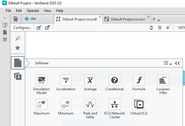
- From the Software palette, select Software » ECU Network Cluster and place the node on the diagram.
- Configure the ECU Network Cluster node.
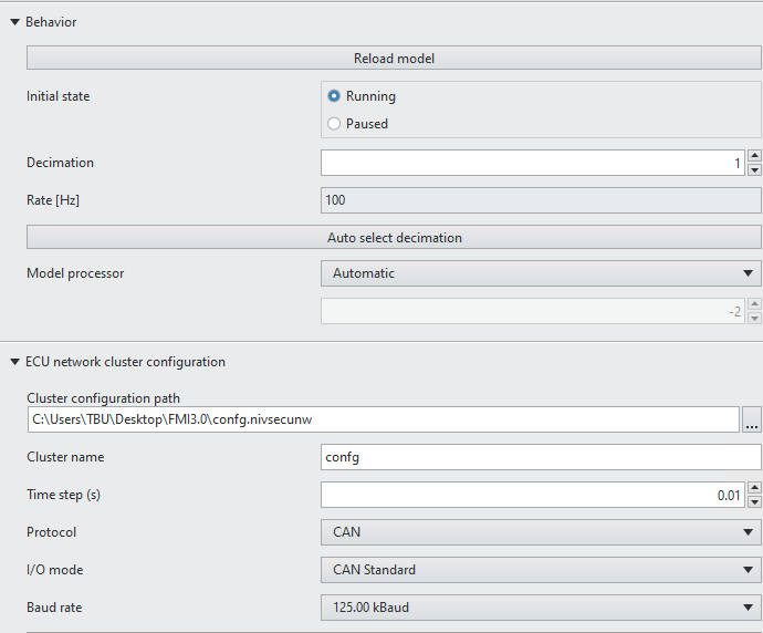
- Decimation: This setting, relative to the PCL, controls how fast the bus updates. Decimation must match the time step in the ECU network cluster configuration. Use the Auto Select Decimation button to configure it easily.
- Cluster configuration path: This path points to the configuration file created when you add the node to the configuration. It stores all the settings.
- Cluster name: This name identifies the cluster in the virtual bus that the node exposes to the real bus. The vECU supplier must provide this name.
- Time step (s): This defines how often the virtual bus refreshes and publishes to the real bus. The minimum value is the PCL rate.
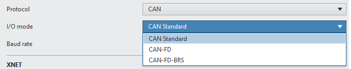
- Protocol: This specifies the interface type to expose, such as CAN, LIN, or Ethernet.
For CAN Only
- I/O mode: This defines the type of CAN to expose.
- Baud rate: This sets the speed of the bus interface.
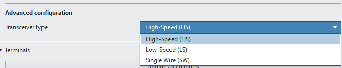
- Transceiver type: This specifies the transceiver type used by the real CAN interface in the system.
For LIN Only
- Baud rate: This sets the speed of the bus interface.
- Virtual Tx frame IDs: These frame IDs are exposed to the real bus.
For Ethernet Only
- Virtual ECU MAC addresses: These MAC addresses identify the ECUs exposed on the real bus.
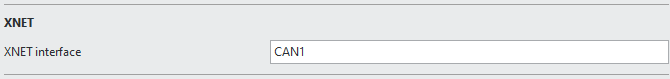
- XNET Interface: This specifies the real interface in the system where the bus will be exposed.
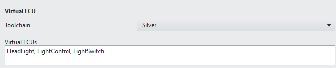
Virtual ECU
- Toolchain:
- Virtual ECUs: This lists all the vECUs in the system configuration that require exposure to the real bus.
After you configure the ECU Network Cluster, the system exposes all messages in the virtual bus to the real bus. Any network analyzer can monitor these messages. In this setup, the DUT receives messages from the vECU, enabling testing in the operational environment. At the same time, the vECU operates based on its compiled code and generates network information for the DUT as defined by its function.
You can include as many ECU Network Clusters as needed in each VeriStand configuration to ensure accurate simulation.