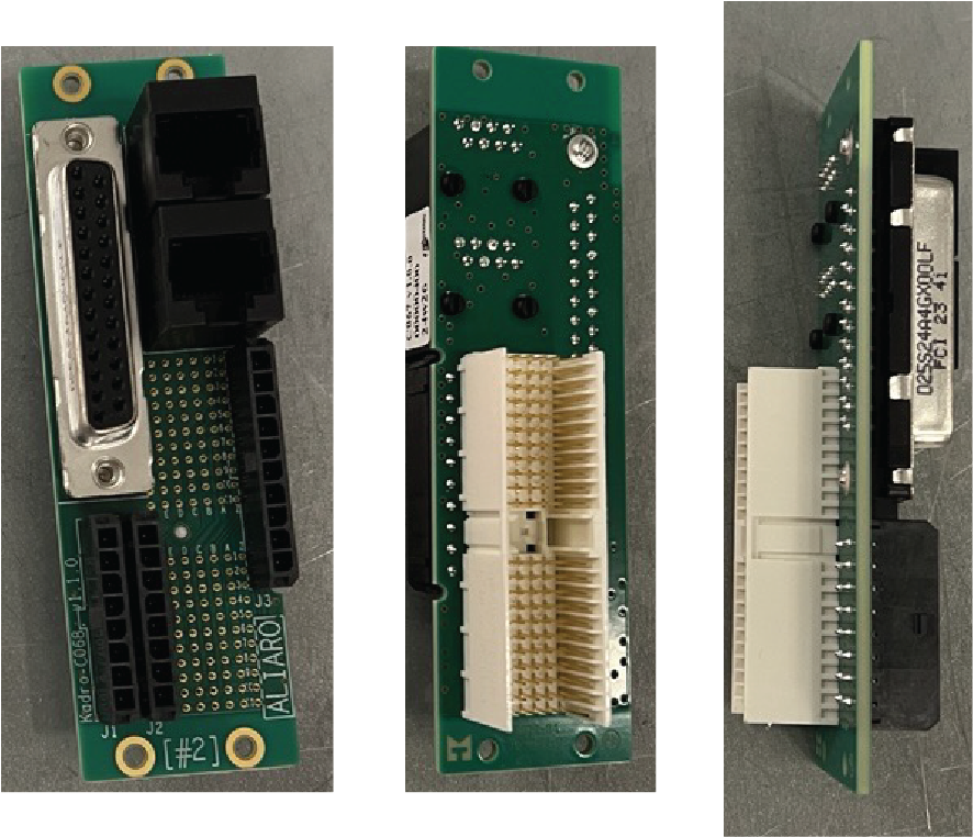
B062 RTI
Use the B062 with the AL-2010 bus switch module for fault insertion on all common vehicle interfaces.
Molex Connectors
J1 Pinout, BUS_IN
| Molex Pin | Connection | Details |
|---|---|---|
| 1 | CH_IN_P1 | |
| 2 | CH_IN_N1 | |
| 3 | CH_IN_P2 | |
| 4 | CH_IN_N2 | |
| 5 | CH_IN_P3 | |
| 6 | CH_IN_N3 | |
| 7 | CH_IN_P4 | |
| 8 | CH_IN_N4 |
J2 Pinout, BUS_OUT
| Molex Pin | Connection | Details |
|---|---|---|
| 1 | CH_OUT_P1 | |
| 2 | CH_OUT_N1 | |
| 3 | CH_OUT_P2 | |
| 4 | CH_OUT_N2 | |
| 5 | CH_OUT_P3 | |
| 6 | CH_OUT_N3 | |
| 7 | CH_OUT_P4 | |
| 8 | CH_OUT_N4 |
J3 Pinout
| Molex Pin | Connection | Details |
|---|---|---|
| 1 | FOI+ | This terminal is the positive rail of an external source. This is typically configured as battery voltage. Voltage input 0 V DC to 60 V DC. |
| 2 | FOI- | This terminal is the negative rail of an external source. This is typically configured as battery voltage. (Voltage input 0 V DC) |
| 3 | RIG+ | External power for module V+ rail. Voltage +24 V. |
| 4 | RIG- | External power for module V- rail. Voltage 0 V. |
| 5 | I2C Out SDA | Do not connect. |
| 6 | I2C Out SCL | Do not connect. |
| 7 | 3.3V | Do not connect. |
| 8 | I2C In SDA | Do not connect. |
| 9 | I2C In SCL | Do not connect. |
| 10 | TS GND | Do not connect. |
J4 Pinout, RJ45#1
| Molex Pin | Connection | Details |
|---|---|---|
| 1 | CH_IN_P5 | |
| 2 | CH_IN_N5 | |
| 3 | CH_IN_P6 | |
| 4 | CH_IN_P7 | |
| 5 | CH_IN_N7 | |
| 6 | CH_IN_N6 | |
| 7 | CH_IN_P8 | |
| 8 | CH_IN_N8 |
J5 Pinout
| Molex Pin | Connection | Details |
|---|---|---|
| 1 | CH_IN_P9 | |
| 2 | CH_IN_N9 | |
| 3 | CH_IN_P10 | |
| 4 | CH_IN_P11 | |
| 5 | CH_IN_N11 | |
| 6 | CH_IN_N10 | |
| 7 | CH_IN_P12 | |
| 8 | CH_IN_N12 |