Hardware-in-the-Loop Transition
The shift from Model-in-the-Loop (MIL) and Software-in-the-Loop (SIL) simulations to Hardware-in-the-Loop (HIL) closed-loop simulation introduces several technical challenges.
- Plant Model and Software under Test Split
- Plant Model Real-time Execution
- Plant Model Harnessing for HIL
- Restbus Simulation and ECU Hardware I/O Interface
- Plant Model Signal Mapping to HIL Physical Channels
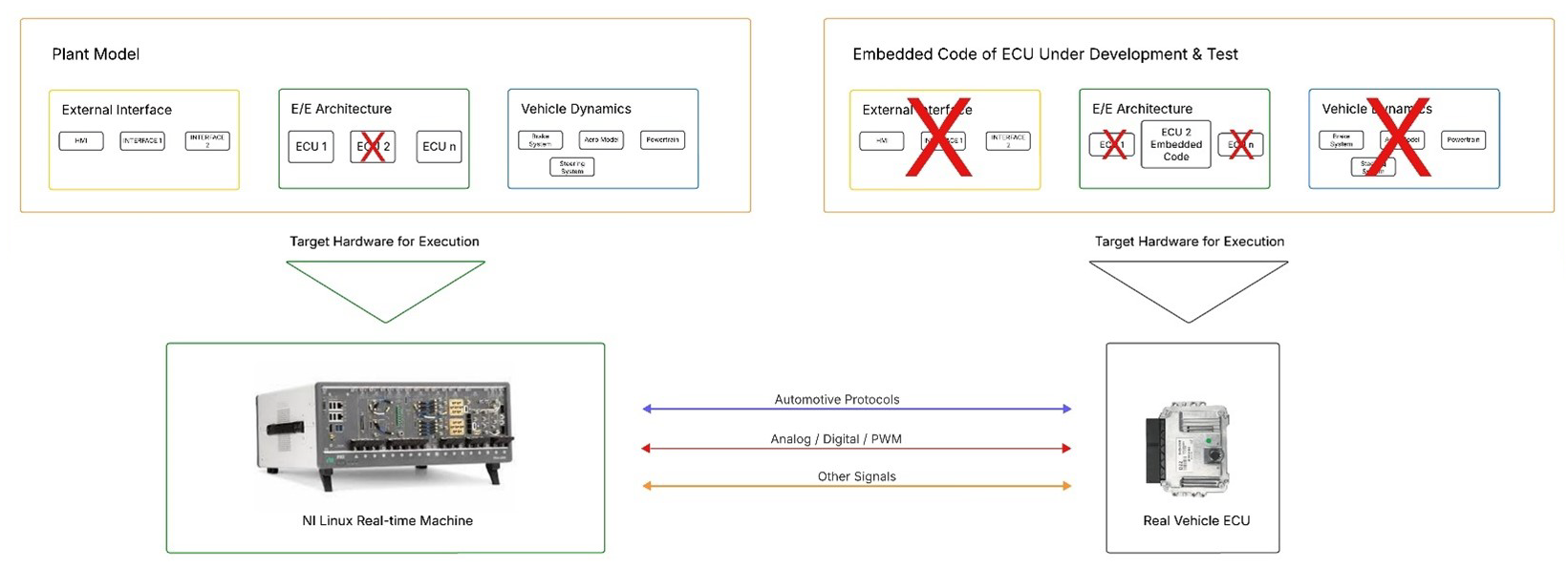
Plant Model and Software under Test Path Split One of the primary changes involves the separation of the plant simulation from the software under test (SUT). In HIL setups, the plant model must be migrated to a dedicated HIL controller to ensure real-time execution. Meanwhile, the SUT is deployed onto the actual ECU hardware.
The following diagram overviews how the model framework execution is split across two different target hardware: Real-time Machine from HIL System and Real Vehicle ECU.
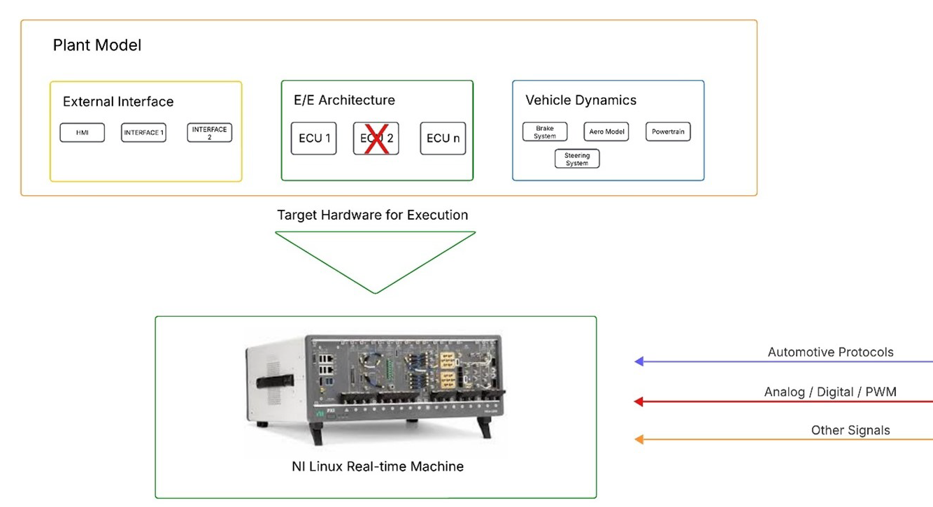
The following images zooms in on the Plant Model section.
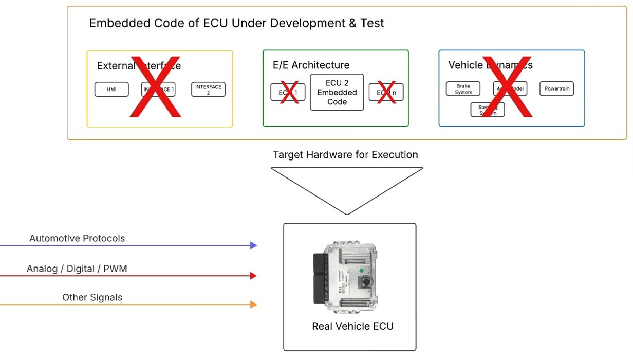
The following images zooms in on the Embedded Code section.
Plant Model Real-time Execution To maintain real-time performance, the choice between using the HIL controller’s CPU or an FPGA board depends on the model’s sampling rate. Typically, models with sampling rates exceeding 10 kHz require FPGA-based execution to meet timing constraints and ensure accurate simulation fidelity.
Plant model real-time execution at the required sampling rate needs also to be verified as the computational resources for its execution could exceed those available from the real-time target.
An implementation of the original model suitable for real-time HIL execution (often known as the HIL implementation model) often leads to the partitioning of the model to enable multicore execution.
Plant Model Harnessing for HIL The HIL implementation model will also need to be harnessed for the HIL system. Model harnessing is about making available in the real-time platform desired model signals and parameters for reading and writing purposes.
Read more about this topic in the Plant Model Preparation section.
Restbus Simulation and ECU Hardware I/O Interface Separating the plant model from the software under test (SUT), which runs on the actual ECU hardware, also requires setting up robust communication between the HIL system hosting the plant simulation and the ECU executing the software application. This communication is facilitated through two primary channels:
- Automotive Protocols: Restbus simulation is employed to enable the plant model to interact over the same automotive communication protocols used by the real ECU, ensuring protocol-level consistency.
- ECU Hardware I/O Interfaces: Signals such as analog, digital, and PWM signals are generated or read by the HIL system to match the ECU physical signal interface requirements, enabling accurate and responsive closed-loop testing.
Plant Model Signal Mapping to HIL Physical Channels Plant model mapping is about signal routing from/to plant model network and ECU HW IO interface to its counterpart from restbus simulation and ECU HW IO physical interface.
Read more about this topic in the Signal Routing and Mapping section.