PXIe-148X Tutorial - Create CSI-2 Packet TDMS Files
This tutorial provides greater detail on how to generate TDMS files using the Create CSI-2 Packet TDMS Files VI for different situations. It provides additional background details on how the VI constructs LLP Packet timestamps based on the control values of the VI.
Table of contents
- Prerequisites
- Create Default TDMS File
- Conceptual Overview
- Determining the Maximum Frame Rate for a Given Frame Size
- Using line sync packets
- Creating a TDMS File with Evenly Spaced Line Packets
- Create CSI-2 Packet TDMS Files VI Reference Help
- Related Documents
Prerequisites
This tutorial is written for users who understand how to perform a basic generation and a basic acquisition with PXIe-148X GMSL or FPD-Link interface modules. It is recommended to complete the PXIe-148X Getting Started Example - Basic Acquisition Tutorial and PXIe-148X Getting Started Example - Basic Generation Tutorial before attempting this tutorial.
Create Default TDMS File
Note: The default scenario below demonstrates the use of this VI. This workflow will be applied with various configurations in additional scenarios that follow.
-
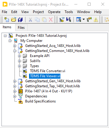
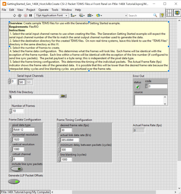
Double-click the Create CSI-2 Packet TDMS Files VI in the LabVIEW project you created in the Basic Generation tutorial.
-
Run the VI to generate the TDMS file using the default settings. This creates a TDMS file for channel SO0 that contains 10 frames at 1920 × 1080 and 30 fps.
Note: During the first run of the VI, the TDMS File Directory control automatically populates with a value pointing to a TDMS Files subfolder. This subfolder is automatically created within the project folder to store any generated TDMS files.
-
Open Windows Explorer and navigate to
<yourprojectdir>\Host\Gen\TDMS Files. The newly created TDMS file has the prefixSI0_to indicate it is associated with the first channel ‘SO0’. Although the prefix contains ‘SI’ suggesting ‘serial input’, when used with the Generation GSE, the TDMS file actually associates with serial output channel ‘SO0’.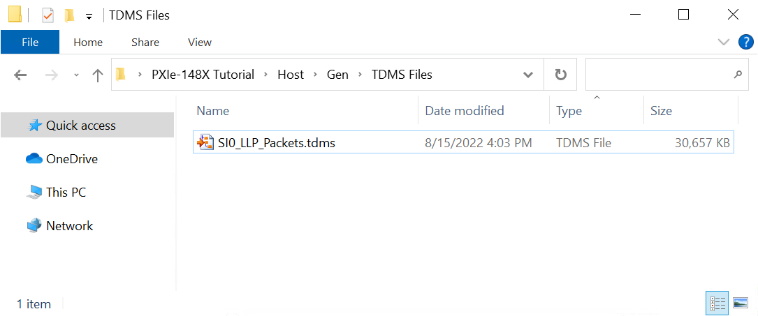
Conceptual Overview
The TDMS file creator generates LLP packet data for use with the Generation Getting Started Example (GSE). To achieve a desired image size and frame rate, the TDMS file creator reads the front panel control values and formats ramp pattern pixel data into CSI-2 LLP packets.
The TDMS file creator uses 5 LLP packet types to facilitate this: Frame Start, Frame End, Line Start, Line End, and Long Packet. If the include line sync packets control is false, the creator generates only Frame Start, Frame End, and Long Packets. To achieve the desired frame rate, the VI sets the timestamps of the LLP packets by calculating the duration of the LLP packet, desired frame period, and interpacket delay.
- To control the duration of an LLP packet, set the pixel data type, horizontal resolution, vertical resolution, and actual link data rate (B/s).
- To control the frame period, set the desired frame rate (fps) control. The frame period is 1 / Frame Rate.
- To control the interpacket delay, set the minimum delay between packets (cycles) and line blanking (cycles).
Note: Packet timing errors occur in the Generataion Example if the interpacket delay of the generated data is too low. Because interpacket delay depends on data path delays and serializer specifications, “too low” is system specific.
Note: If you set number of frames very high, it can take a long time to iterate on configuration settings. The VI does not calculate actual fps until after the TDMS files have been generated. If you create a massive file, you can run out of disk space and thus not get a valid data set.
If the interpacket delay and packet duration of the packets is greater than the desired frame period, the generated output files will not achieve the desired frame rate. The VI updates the Actual Frame Rate (fps) indicator after creating the TDMS files to display the final frame rate achieved.
The interpacket delay in a generated TDMS file is largely goverened by the value of minimum delay between packets (cycles) and line blanking (cycles) and the rules defined below:
- Min Delay = minimum delay between packets (cycles)
- Max Delay = the greater of minimum delay between packets (cycles) and line blanking (cycles)
- Long Packet following a Long Packet has Max Delay
- Line End or Frame End following a long packet has Min Delay
- Any packet following a Frame Start, Frame End, or Line Start has Min Delay
- Line Start following a Line End has Max Delay
- Frame End following Line End has Min Delay
The rules above can be summarized to:
| Current Packet | Next Packet | Delay (cycles) between end of Current and start of Next Packet |
|---|---|---|
| Frame Start | Line Start | Min Delay |
| Frame Start | Long Packet | Min Delay |
| Frame End | Frame Start | Determined by desired frame rate, but must be at least equal to Min Delay |
| Line Start | Long Packet | Min Delay |
| Line End | Line Start | Max Delay |
| Line End | Frame End | Min Delay |
| Long Packet | Long Packet | Max Delay |
| Long Packet | Line End | Min Delay |
| Long Packet | Frame End | Min Delay |
The figure below shows what the timing of the generated LLP packets looks like with include line sync packets set to false. 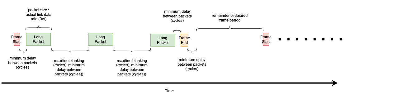
The figure below shows what the timing of the generated LLP packets looks like with include line sync packets set to true. 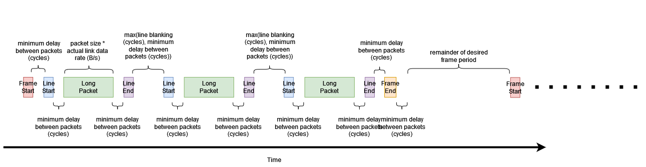
The following scenarios illustrate these concepts in more detail.
Determining the Maximum Frame Rate for a Given Frame Size
You can use the Create CSI-2 Packet TDMS Files VI to easily determine a theoretical maximum frame rate for a given frame size. The frame rate shown in the Actual Frame Rate (fps) indicator is influenced by the Frame Data Configuration and Frame Timing Configuration controls. This section walks through how to adjust specific controls to achieve the theoretical maximum frame rate for a given frame size.
Note: For the purposes of this tutorial, all input control values not specified should be left with their default values.
-
Double click the Create CSI-2 Packet TDMS Files VI in the LabVIEW project.
-
Set the Number of Frames control to 1. Setting this to 1 lets you quickly iterate over configuration settings and get feedback with the Actual Frame Rate (fps) indicator.
-
Set the desired frame rate (fps) to 1000. This makes the frame period much smaller than the interpacket delay and LLP packet duration.
-
Run the VI and view the Actual Frame Rate (fps) indicator. This indicator tells you the maximum achieveable FPS for a given Frame Data Configuration and Frame Timing Configuration.
-
Now the set the desired frame rate (fps) to 40. This makes the frame period larger than the frame perod required for the interpacket delay and LLP packet duration.
-
Run the VI and view the Actual Frame Rate (fps) indicator. It shows 40 fps.
-
Double-click the TDMS File Viewer VI in the LabVIEW project.
-
Select the correct location for the TDMS File Directory control. By default, TDMS files generated are saved to
<yourprojectdir>\Host\Gen\TDMS Files.Note: The directory browse window does not show the TDMS files located in the “TDMS Files” directory.
-
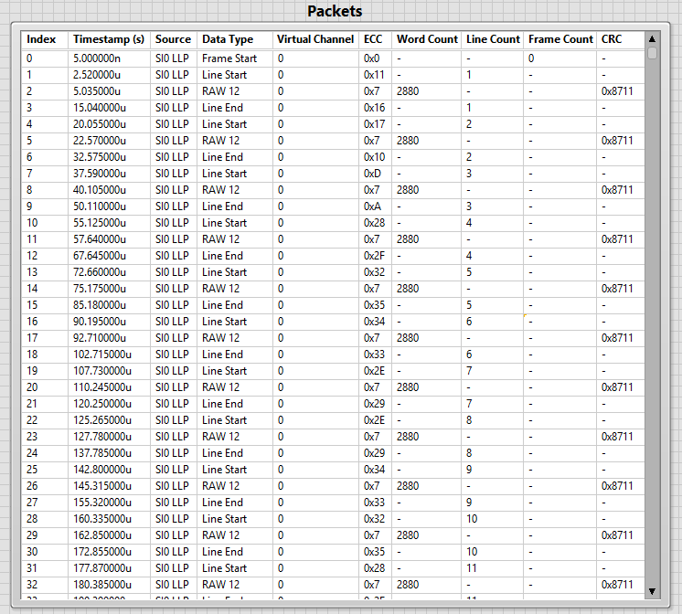
Run the TDMS File Viewer VI and verify that you have one frame of data. You should have a Frame Start packet, followed by 1080 RAW12 packets, followed by a Frame End packet.
-
Repeat steps 3 and 4 with a horizontal resolution of 3840 and a vertical resolution of 2160. Observe that the Actual Frame Rate (fps) should be 23.1642. The achievable frame rate has decreased because the duration of the Long Packets and the number of Long Packets has increased.
-
Repeat steps 7 through 9. You should see within the TDMS File Viewer that there is a Frame Start packet, followed by 2160 RAW12 packets, followed by a Frame End packet.
Using line sync packets
This section enables line sync packets in the generated data and uses the TDMS file viewer to verify that each RAW12 Long Packet is proceded by a Line Start packet and followed by a Line End packet.
Note: For the purposes of this procedure, all input control values not specified should be left with their default values.
-
Double-click the Create CSI-2 Packet TDMS Files VI in the LabVIEW project.
-
Set the Number of Frames control to 1.
-
Set the desired frame rate (fps) to 1000.
-
Run the VI, view the Actual Frame Rate (fps) indicator, and note the FPS displayed.
-
Set the include line sync packets control to true (illuminated).
-
Run the VI, view the Actual Frame Rate (fps) indicator, and note the FPS displayed is slightly lower than before. This is because more packets are being sent and more minimum delays are being added to each frame.
-
Double-click the TDMS File Viewer VI in the LabVIEW project.
-
Select the correct location for the TDMS File Directory control. By default, TDMS files generated are saved to
<yourprojectdir>\Host\Gen\TDMS Files. -
Run the TDMS File Viewer VI and verify that all of the RAW12 Long Packets are surrounded by Line Start and Line End packets. The display should resemble the image below.
Creating a TDMS File with Evenly Spaced Line Packets
By default, the Create CSI-2 Packet TDMS Files VI produces a TDMS file that tightly groups together all the packets in a frame while still meeting the configuration requirements. This behavior leaves any remaining time in the frame period empty. However, many cameras stream data more evenly across the frame period, and, if desired, you can configure the Create CSI-2 Packet TDMS Files VI to more closely approximate that behavior. Data sets with higher interpacket delays are easier for the Generation Example to run without packet timing errors.
This procedure shows you how to adjust the interpacket delay to distribute line packets evenly throughout the frame period. You will use the TDMS File Viewer VI to examine the packets to see how you can adjust the timing to achieve a 30 fps TDMS file.
Note: For the purposes of this tutorial, all input control values not specified should be left with their default values.
-
Double-click the Create CSI-2 Packet TDMS Files VI in the LabVIEW project.
-
Set the Number of Frames control to 2. Two frames are necessary so that you can view the entire frame period, which is measured from a Frame Start packet to the next Frame Start packet.
-
Set the desired frame rate (fps) to 30.
-
Run the VI, view the Actual Frame Rate (fps) indicator, and note that the FPS displayed is 30.
-
Double-click the TDMS File Viewer VI in the LabVIEW project.
-
Select the correct location for the TDMS File Directory control. By default, the generated TDMS files are saved to
<yourprojectdir>\Host\Gen\TDMS Files. -
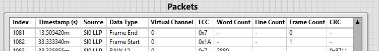
Run the TDMS File Viewer VI and view the timestamps of the first Frame End and second Frame Start packets on packet indexes 1081 and 1082. Note that there is a remaining frame period of 20 milliseconds. You can adjust the interpacket delay so that there is more time between each line packet while still achieving 30 fps. Note the image below.
-
Set the line blanking (cycles) to 4650 and regenerate the TDMS file. Actual Frame Rate (fps) should remain 30 fps.
-
Run the TDMS File Viewer VI and view the Frame End and Frame Start packets on packet indexes 1081 and 1082. There should now be a very small remaining frame period. You have successfully moved that delay from the end of the frame period to between each of the packets.
Create CSI-2 Packet TDMS Files VI Reference Help
General
- Serial Input Channels - Array of strings representing the channels for which you will generate TDMS files. Generated TDMS files have the prefix SIx_ to indicate it is associated with a channel SOx. Although the prefix contains SI suggests ‘serial input’, when used with the Generation GSE, the TDMS file actually associates a specific serial output channel e.g. SO0.
- TDMS File Directory - Path to the directory used to load TDMS data files.
If left blank, TDMS File Directory is automatically populated with a path to a TDMS Files subfolder within the getting started example root directory. TDMS data files include files for LLP packet data, I2C timestamps, and GPIO timestamps.
- Number of Frames - Number of frames to generate.
- Actual Frame Rate (fps) - Calculated frame rate based on Frame Data Configuration and Frame Timing Configuration control values. This value may differ from the desired frame rate (fps) depending on other control values.
- Error Out - Displays any error that occurred while running the VI.
Frame Data Configuration
- pixel data type - Data type of the LLP packet payload for long packets.
Supported Options: YUV420 8-bit, YUV420 10-bit, Legacy YUV420 8-bit, YUV420 8-bit Chroma Shifted, YUV420 10-bit Chroma Shifted, YUV422 8-bit, YUV422 10-bit, RGB565, RGB666, RGB888, RAW 8, RAW 10, RAW 12, RAW 14, RAW 16.
- horizontal resolution - Number of pixels, from left to right, of a generated frame. Each long packet that is generated has a payload that contains the number of pixels defined by this value.
- vertical resolution - Number of pixels, from top to bottom, of a generated frame. Each frame that is generated has a number of long packets equal to this value.
- virtual channel - Number representing a Virtual Channel Identifier.
A virtual channel identifier designates separate logical channels for data flows that are interleaved in the data path.
- include line sync packets - Determines whether each generated Long Packet is preceded by a Line Start Packet and followed by a Line End packet.
Frame Timing Configuration
- desired frame rate (fps) - Target frame rate for generated TDMS data.
-
actual link data rate (B/s) - Maximum link rate of the serializer. Refer to the table below.
Serializer Theoretical Max Practical Max DS90UB953 400MB/s 385 MB/s MAX9295A 750MB/s 600 MB/s Practical maxes have been determined empirically. You may find that the values are higher or lower depending on your application. Refer to Automotive Camera Module Variants Table to associate a serializer with a specific interface module.
- minimum delay between packets (cycles) - Minimum number of cycles of delay between LLP packets. Refer to the Conceptual Overview for additional detail.
- line blanking (cycles) - Minimum number of cycles of delay between lines in a frame. Refer to the Conceptual Overview for additional detail.